
Posts
-
Sudoku Solver AR Part 4: Camera Capture (Linux)
This post is part of a series where I explain how to build an augmented reality Sudoku solver. All of the image processing and computer vision is done from scratch. See the first post for a complete list of topics.
Capturing video on Linux is done using the Video for Linux (V4L2) API. It’s actually a really nice API and very well documented. I encourage you to check out the documentation if you need to do something I don’t cover here.
I’m going to go over how to find all of the connected cameras, query their supported formats, the simplest method to get a video frame, and convert it to an RGB image.
List Connected Cameras
Cameras on Linux show up as files in the
/devdirectory. They are always listed in the formatvideo{number}where {number} can be any number from 0 to 255. Finding all of the connected cameras is as simple as searching the/devdirectory for filenames that start withvideo.#include <experimental/filesystem> #include <vector> ... //Find all of the files in the "/dev" directory that start with "video". std::vector<std::experimental::filesystem::path> videoDevicePaths; for(const auto& directoryEntry : std::experimental::filesystem::directory_iterator("/dev")) { const std::string fileName = directoryEntry.path().filename().string(); if(fileName.find("video") == 0) videoDevicePaths.push_back(directoryEntry); }I’m using the C++17 Filesystem library here for convenience. If you’re using an older compiler, you can use the Boost Filesystem library or readdir.
Querying Supported Formats
Cameras capture video frames in different sizes, pixel formats, and rates. You can query a camera’s supported formats to find the best fit for your use or just let the driver pick a sane default.
There’s certainly an advantage to picking the formats yourself. For example, since cameras rarely provide an RGB image, if a camera uses a format that you already know how to convert to RGB, you can save time and use that instead. You can also choose to lower the frame rate for better quality at a cost of more motion blur or raise the frame rate for a more noisy image and less motion blur.
The first thing you need to do to query a camera is to open the camera and get a file descriptor. This file descriptor is then used to refer to that specific camera.
#include <fcntl.h>
#include <sys/stat.h>
#include <sys/types.h>

...

//Select one of the enumerated cameras from above.
const std::string videoDevicePath = videoDevicePaths[0].string();

//Get a file descriptor for the device.
const int fd = open(videoDevicePath.c_str(),O_RDONLY);
if(fd == -1)
{
    std::cerr << "Could not open video device: " << videoDevicePath << std::endl;
    return false;
}
When you’re done using the camera, don’t forget to close the file descriptor.
//Close the file descriptor later when done using the camera.
close(fd);
All camera querying and configuration is done using the ioctl function. It’s used by passing an open file descriptor for the device, a constant that indicates the operation to be performed, and a pointer to some type depending on the indicated operation1.
Three different versions of
ioctlare used to query the formats supported by a camera. They give the supported pixel formats, sizes (width and height), and frame intervals2. Querying is done in this same order. That is, each pixel format has its own supported frame sizes which then further restricts the supported frame intervals.The pixel format is queried by calling
ioctlwithVIDIOC_ENUM_FMTas the second argument and a pointer to av4l2_fmtdescstruct as the third argument. Thev4l2_fmtdescstruct has an index field that indicates which pixel format is populated into the struct by theioctlcall. The index is then incremented andioctlis called again until it returns an error code indicating that there are no more supported formats.#include <sys/ioctl.h> #include <sys/mman.h> ... //Enumerate all supported pixel formats by incrementing the index field until ioctl //returns an error. v4l2_fmtdesc fmtDesc; fmtDesc.index = 0; //Start index. fmtDesc.type = V4L2_BUF_TYPE_VIDEO_CAPTURE; //Must be set to V4L2_BUF_TYPE_VIDEO_CAPTURE. for(;ioctl(fd,VIDIOC_ENUM_FMT,&fmtDesc) != -1;fmtDesc.index++) { //Format identifier used for querying or selecting the format to use. It can be //anything from RGB, YUV, JPEG, or more. const unsigned int pixelFormat = fmtDesc.pixelformat; //Human readable version of pixel format that can be displayed to the user. const unsigned char* humanReadablePixelFormat = fmtDesc.description; }The list of possible pixel formats are found in the documentation.
Getting a list of supported sizes is a little trickier. You start by calling
ioctlwithVIDIOC_ENUM_FRAMESIZESand a pointer to av4l2_frmsizeenumstruct. But after the first call, you need to check if frame sizes are discrete or given as a minimum and maximum that can be adjusted in some step size.//Call once to figure out how frame sizes are specified. v4l2_frmsizeenum frameSizeEnum; frameSizeEnum.index = 0; //Start index. frameSizeEnum.pixel_format = pixelFormat; //A supported pixel format must be specified! if(ioctl(fd,VIDIOC_ENUM_FRAMESIZES,&frameSizeEnum) == -1) return false; //Frame sizes are specified in discrete units (eg. 320x240 and 640x480). if(frameSizeEnum.type == V4L2_FRMSIZE_TYPE_DISCRETE) { //Iterate through remaining sizes. do { const unsigned int width = frameSizeEnum.discrete.width; const unsigned int height = frameSizeEnum.discrete.height; //Make use of width and height here. frameSizeEnum.index += 1; } while(ioctl(fd,VIDIOC_ENUM_FRAMESIZES,&frameSizeEnum) != -1); } //Frame sizes are specified as individual ranges where each size is a fixed step //difference from one another. Say the width is specified with a range from 32 to 96 in //16 pixel steps, then the supported widths would be 32, 48, 64, 80, and 96. else if(frameSizeEnum.type == V4L2_FRMSIZE_TYPE_STEPWISE || frameSizeEnum.type == V4L2_FRMSIZE_TYPE_CONTINUOUS) { //The only difference between V4L2_FRMSIZE_TYPE_STEPWISE and //V4L2_FRMSIZE_TYPE_CONTINUOUS is the step size of continuous is always 1. //Iterate through every possible size. for(unsigned int height = frameSizeEnum.stepwise.min_height; height <= frameSizeEnum.stepwise.max_height; height += frameSizeEnum.stepwise.step_height) { for(unsigned int width = frameSizeEnum.stepwise.min_width; width <= frameSizeEnum.stepwise.max_width; width += frameSizeEnum.stepwise.step_width) { //Make use of width and height here. } } }Finally, the list of supported frame intervals is very similar to getting frame sizes. Call
ioctlwithVIDIOC_ENUM_FRAMEINTERVALSand a pointer to av4l2_frmivalenumstruct. The frame intervals can be given in discrete chunks, incremental steps, or any value within a specified range.//Similar to above, call once to figure out how frame intervals are specified. v4l2_frmivalenum frameIntervalEnum; frameIntervalEnum.index = 0; frameIntervalEnum.pixel_format = pixelFormat; //A supported pixel format must be specified! frameIntervalEnum.width = width; //A supported width and height must be specified! frameIntervalEnum.height = height; if(ioctl(fd,VIDIOC_ENUM_FRAMEINTERVALS,&frameIntervalEnum) == -1) return false; //Frame intervals are specified in discrete units. if(frameIntervalEnum.type == V4L2_FRMIVAL_TYPE_DISCRETE) { //Iterate through remaining frame intervals. do { assert(frameIntervalEnum.discrete.denominator != 0); const float interval = static_cast<float>(frameIntervalEnum.discrete.numerator) / static_cast<float>(frameIntervalEnum.discrete.denominator); //Make use of interval here. frameIntervalEnum.index += 1; } while(ioctl(fd,VIDIOC_ENUM_FRAMEINTERVALS,&frameIntervalEnum)); } //Frame intervals are available in fixed steps between the min and max, including the ends. else if(frameIntervalEnum.type == V4L2_FRMIVAL_TYPE_STEPWISE) { assert(frameIntervalEnum.stepwise.min.denominator != 0); assert(frameIntervalEnum.stepwise.max.denominator != 0); assert(frameIntervalEnum.stepwise.step.denominator != 0); const float stepMin = static_cast<float>(frameIntervalEnum.stepwise.min.numerator) / static_cast<float>(frameIntervalEnum.stepwise.min.denominator); const float stepMax = static_cast<float>(frameIntervalEnum.stepwise.max.numerator) / static_cast<float>(frameIntervalEnum.stepwise.max.denominator); const float stepIncr = static_cast<float>(frameIntervalEnum.stepwise.step.numerator) / static_cast<float>(frameIntervalEnum.stepwise.step.denominator); for(float interval = stepMin;interval <= stepMax;interval += stepIncr) { //Make use of interval here. } } //Any frame interval between the min and max are okay, including the ends. else if(frameIntervalEnum.type == V4L2_FRMIVAL_TYPE_CONTINUOUS) { assert(frameIntervalEnum.stepwise.min.denominator != 0); const float intervalMin = static_cast<float>(frameIntervalEnum.stepwise.min.numerator) / static_cast<float>(frameIntervalEnum.stepwise.min.denominator); assert(frameIntervalEnum.stepwise.max.denominator != 0); const float intervalMax = static_cast<float>(frameIntervalEnum.stepwise.max.numerator) / static_cast<float>(frameIntervalEnum.stepwise.max.denominator); //Make use of intervals here. }Selecting a Format
Setting the camera to use a particular format and size is done by filling out a
v4l2_formatstruct and passing it to aioctlcall withVIDIOC_S_FMT. If you don’t specify a supported format and size, the driver will select a different one and modify thev4l2_formatstruct to indicate what’s being used instead.//Set the width, height, and pixel format that should be used. If a format is not //supported, the driver will select something else and modify the v4l2_format //structure to indicate the change. v4l2_format format; format.type = V4L2_BUF_TYPE_VIDEO_CAPTURE; //Must be set to V4L2_BUF_TYPE_VIDEO_CAPTURE. format.fmt.pix.width = width; format.fmt.pix.height = height; format.fmt.pix.pixelformat = pixelFormat; format.fmt.pix.field = V4L2_FIELD_NONE; //Non-interlaced. format.fmt.pix.bytesperline = 0; //Depends on pixel format but can be larger to pad extra //bytes at the end of each line. Set to zero to get a //reasonable default. if(ioctl(fd,VIDIOC_S_FMT,&format) == -1) return false; //Driver sets the size of each image in bytes. const unsigned int imageSizeInBytes = format.fmt.pix.sizeimage;After you set the format and size, you can change the frame interval as well. If you change this first, it might be reset to a default value. You can also reset it to default by setting the numerator and denominator to zero.
//Set the frame interval that should be used.
v4l2_streamparm streamParm;
memset(&streamParm,0,sizeof(streamParm));
streamParm.type = V4L2_BUF_TYPE_VIDEO_CAPTURE; //Must be set to V4L2_BUF_TYPE_VIDEO_CAPTURE.
streamParm.parm.capture.timeperframe.numerator = intervalNumerator;
streamParm.parm.capture.timeperframe.denominator = intervalDenominator;
if(ioctl(fd,VIDIOC_S_PARM,&streamParm) == -1)
    return false;
Capturing a Video Frame
There are multiple ways to capture a frame of video using V4L2. The simplest method is to just read from the file descriptor like it’s a file. Every
sizeimage(returned by theioctl(fd,VIDIOC_S_FMT,...);call) bytes read represents a single frame. Remember that the pixel format is probably not RGB so it usually needs to be converted before it can be used.#include <unistd.h> ... //Simply read from the file descriptor into a buffer. Every `imageSizeInBytes` (defined //above) read is one frame. std::vector<unsigned char> buffer(imageSizeInBytes); const ssize_t bytesRead = read(fd,&buffer[0],buffer.size()); if(bytesRead == -1) return false;Converting a Video Frame To RGB
Since the pixel format is not RGB and we need RGB, it obviously needs to be converted. The process varies by format, so I’m going to only go over one format here: YUYV 4:2:2.
The YUYV 4:2:2 format is a Y’CbCr interleaved format where every pixel has its own luminance (Y’) channel and every two pixels share the Cb and Cr channels. Its layout is a repeating pattern that looks like this: `[Y’_0, C_b, Y’_1, C_r, Y’_0, C_b, Y’_1, C_r,…]`. Where `Y’_0` is luminance for the first pixel, `C_b` is the Cb channel, `Y’_1` is lumiance for the second pixel, and `C_r` is the Cr channel.
The actual Y’CbCr to RGB conversion can be done by following the JPEG standard which is good enough because we are assuming all cameras are uncalibrated.
`R = Y’ + 1.402 * (Cr - 128)`
`G = Y’ - 0.344 * (Cb - 128) - 0.714 * (Cr - 128)`
`B = Y’ + 1.772 * (Cb - 128)`
Since this format specifies two Y’ for every pair of Cb and Cr, it’s easiest to do the actual conversion to two pixels at a time.
const unsigned int imageWidth; //Width of image.
const unsigned int imageHeight; //Height of image.
const std::vector<unsigned char> yuyvData; //Input YUYV buffer read from camera.
std::vector<unsigned char> rgbData(imageWidth * imageHeight * 3); //Output RGB buffer.

//Convenience function for clamping a signed 32-bit integer to an unsigned 8-bit integer.
auto ClampToU8 = [](const int value)
{
    return std::min(std::max(value,0),255);
};

//Convert from YUYV 4:2:2 to RGB using two pixels at a time.
for(unsigned int x = 0;x < imageWidth * imageHeight;x += 2)
{
    const unsigned int inputIndex = x * 2;
    const unsigned int outputIndex = x * 3;

    //Extract pixel's YCbCr components.
    const unsigned char y0 = yuyvData[inputIndex + 0];
    const unsigned char cb = yuyvData[inputIndex + 1];
    const unsigned char y1 = yuyvData[inputIndex + 2];
    const unsigned char cr = yuyvData[inputIndex + 3];

    //Convert first pixel.
    rgbData[outputIndex + 0] = ClampToU8(y0 + 1.402 * (cr - 128));
    rgbData[outputIndex + 1] = ClampToU8(y0 - 0.344 * (cb - 128) - 0.714 * (cr - 128));
    rgbData[outputIndex + 2] = ClampToU8(y0 + 1.772 * (cb - 128));

    //Convert second pixel.
    rgbData[outputIndex + 3] = ClampToU8(y1 + 1.402 * (cr - 128));
    rgbData[outputIndex + 4] = ClampToU8(y1 - 0.344 * (cb - 128) - 0.714 * (cr - 128));
    rgbData[outputIndex + 5] = ClampToU8(y1 + 1.772 * (cb - 128));
}
Now the image is ready to be displayed or processed further. Working with a single camera on a single platform isn’t too much work. Expanding to support more, however, can be very time consuming. I highly recommend using a library that handles most of this for you. Next time, I’m going to ignore my own advice and show how to capture video frames from a camera on Windows.
Resources
Footnotes
-
The function definition is actually
int ioctl(int fd, unsigned long int request, ...);. This indicates that the function takes two or more arguments but we only need the format that takes exactly three arguments. ↩ -
Frame interval is the time between successive frames. Frames per second is equal to 1 / frame interval. ↩
-
-
Sudoku Solver AR Part 3: A Crash Course in Image Processing
This post is part of a series where I explain how to build an augmented reality Sudoku solver. All of the image processing and computer vision is done from scratch. See the first post for a complete list of topics.
Image processing is the manipulation of images to produce new images or info about said images. Here I will quickly go over the fundamentals needed to develop a process to recognize Sudoku puzzles (then we’ll be only a skip away from general object recognition and ultimately the robot apocalypse, good times).
Images
When you look at a typical colored image on your computer screen, it’s generally made up of thousands or millions of dots using various mixtures of red, green, and blue light. Each of these colors represent a channel in an image. Images can be made up of other channels like alpha, used for compositing, but that’s not needed here. A collection of these channels representing a point in an image is called a pixel.
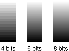
Each color in each channel is made up of so many bits. Most computer images use 8-bits in an unsigned format for `2^8 = 256` different values or shades. Where higher values are usually defined to appear brighter or have a greater intensity. Increasing the number of bits makes the apparent change between different shades of a color smoother. There are also other formats like floats which are clamped to between 0.0 (none) and 1.0 (full intensity) before being displayed.
Images are usually laid out in memory as large continuous blocks. The dimensions used to describe these blocks (think width and height) determines if an image is 1D, 2D (most common and the only type used here), 3D, or something else entirely. The channels can be interleaved (RGBRGBRGBRGB…) or in continuous chunks (RRR…GGG…BBB…). The beginning is usually the top left of the image and successive elements are found in a left-to-right and then top-to-bottom order. Although, some libraries and image storage formats expect the rows in a reversed bottom-to-top order. Accessing a particular pixel’s color channel using an X and Y coordinate is done using a straight forward formula1.
Format Example How to calculate an offset Interleaved RGBRGBRGB `text{offset} = (y * text{image}_text{width} + x) * text{channel}_text{count} + text{channel}_text{index}` Chunked RRRGGGBBB `text{offset} = text{channel}_text{index} * text{image}_text{width} * text{image}_text{height} + y * text{image}_text{width} + x` When a camera captures an image, extra processing is almost always done by the hardware2. When done automatically, this processing becomes a characteristic of the camera. Unfortunately, this can be a problem for some image processing algorithms. Since it’s not a problem for the algorithms used in this project, the extra processing won’t be covered here. But, it’s worth investigating if you plan to work on, for example, scientific image processing where you have control over the types of cameras being used.
Color Models and Spaces
There are other ways to represent color than just mixing shades of red, green, and blue (RGB) light. For example, painters mix cyan, magenta, and yellow (CMY) together to form other colors. Another method is to refer to a color by its hue, saturation, and lightness (HSL). These are all examples of color models. Some color models, such as RGB and HSL, allow colors to be converted between one another at a cost of computational precision. In other cases, colors cannot be directly converted, like RGB and CMY, so a much more complicated transform is necessary to match colors that appear similar.


Color spaces describe how a specific color should be perceived. They’re usually defined as a range of colors relative to what can be perceived by humans. Supporting all visible colors doesn’t always make sense. For example, your computer screen cannot display many shades of green that you have no problem seeing (unless you have a vision disability like being color blind). The important take away for color spaces is that if you have an 8-bit RGB value (eg. (255,128,23)) in one color space and the same RGB value in another color space, they don’t necessarily represent the same perceived color.
The industry has standardized around the idea that for any RGB image where a color space is not provided, it’s assumed to use the sRGB color space. Since this project is expected to work with any random camera, this is also the color space assumed for RGB images here. Finding the actual color space of a camera requires a calibration process that is outside the scope of this post.
Basic Image Processing Patterns
Most of our image processing operations are based on one of two patterns. The first modifies each each pixel independently. Usually in sequential order, for simplicity and cache-efficiency, but order doesn’t really matter. For example, the following copies the red channel value to the green and blue channels to create a type of greyscale image.
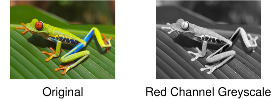
constexpr unsigned int RED_CHANNEL_OFFSET = 0;
constexpr unsigned int GREEN_CHANNEL_OFFSET = 1;
constexpr unsigned int BLUE_CHANNEL_OFFSET = 2;
constexpr unsigned int CHANNEL_COUNT = 3;

Image image; //RGB interleaved, unsigned 8-bits per channel.
const unsigned int pixelCount = image.width * image.height;

//Iterate over every pixel.
for(unsigned int x = 0;x < pixelCount;x++)
{
    //Offset to the current pixel.
    const unsigned int index = x * CHANNEL_COUNT;

    //Copy the value in the red channel to both the green and blue channels.
    const unsigned char redValue = image.data[index + RED_CHANNEL_OFFSET];
    image.data[index + GREEN_CHANNEL_OFFSET] = redValue;
    image.data[index + BLUE_CHANNEL_OFFSET] = redValue;
}
The second pattern involves accessing not just a particular pixel, but also the surrounding pixels, to perform an operation known as a convolution. These surrounding pixels are usually accessed in a square shape where each side is some odd number so it fits symmetrically over the center pixel. The center pixel and all surrounding pixels are multiplied by a number defined as part of a kernel and then summed. This summed value then becomes the new value for the center pixel.
You might be wondering: what should be done when the surrounding pixels don’t exist because they are outside the boundary of the image? It completely depends on the operation being performed and how the result is going to be used. Sometimes the edges are not important so the pixels are just skipped. Other times, a clamping behavior is performed so the closest valid pixels are used. There are also algorithms that adapt by changing their behavior such as accessing less pixels and using different kernels.
Here is an example where the edges are ignored and the kernel computes an average to produce a blurred version of the original image.

constexpr unsigned int KERNEL_RADIUS = 2;
constexpr unsigned int KERNEL_DIAMETER = KERNEL_RADIUS * 2 + 1;
constexpr unsigned int KERNEL_SIZE = KERNEL_DIAMETER * KERNEL_DIAMETER;
constexpr unsigned int CHANNEL_COUNT = 3;

Image inputImage; //RGB interleaved, unsigned 8-bits per channel.
Image outputImage; //Same size and format as input image.
const unsigned int rowSpan = inputImage.width * CHANNEL_COUNT;

//Convenience function for getting the pixel of an image at a specific coordinate.
auto GetPixel = [](Image& image,const unsigned int x,const unsigned int y)
{
    assert(x < image.width && y < image.height);

    return &image.data[(y * image.width + x) * CHANNEL_COUNT];
};

//Perform blur convolution on every pixel where the kernel fits completely within the
//image.
for(unsigned int y = KERNEL_RADIUS;y < inputImage.height - KERNEL_RADIUS;y++)
{
    for(unsigned int x = KERNEL_RADIUS;x < inputImage.width - KERNEL_RADIUS;x++)
    {
        //Sum centered and surrounding pixels. Each channel is done individually.
        float sum[CHANNEL_COUNT] = {0.0f};
        for(unsigned int i = 0;i < KERNEL_DIAMETER;i++)
        {
            for(unsigned int j = 0;j < KERNEL_DIAMETER;j++)
            {
                const unsigned char* pixel = GetPixel(inputImage,
                                                      x - KERNEL_RADIUS + j,
                                                      y - KERNEL_RADIUS + i);
                for(unsigned int c = 0;c < CHANNEL_COUNT;c++)
                {
                    sum[c] += pixel[c];
                }
            }
        }

        //Use the sums to compute the average of the centered and surrounding pixels. This
        //is equivalent to a kernel where every entry in the kernel is 1 / KERNEL_SIZE.
        for(unsigned int c = 0;c < CHANNEL_COUNT;c++)
        {
            unsigned char* pixel = GetPixel(outputImage,x,y);
            pixel[c] = std::lrint(sum[c] / static_cast<float>(KERNEL_SIZE));
        }
    }
}
Notice in this example that there are separate input and output images. Because convolutions require the original pixels, modifying the original image in place would produce a completely different and incorrect result.
Greyscale
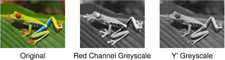
Many image processing operations expect to work with greyscale images. An earlier example created a greyscale image by copying the red channel to the green and blue channels. When the red, green, and blue channels are equal, the resulting image appears as various shades of grey. There are many different ways to create greyscale images, each with their own aesthetic and technical benefits.
A good choice because it’s easy to implement and makes use of red, green, and blue channels is Y′ (luma) from the YUV color model. Following the BT.601 specification, Y′ can be found using the following formula.
`Y′ = 0.299 * text{Pixel}_R + 0.587 * text{Pixel}_G + 0.114 * text{Pixel}_B`
The code is very similar to the previous greyscale example. Simply iterate over each pixel individually, calculate Y′, and assign the resulting value to the red, green, and blue channels.
constexpr unsigned int RED_CHANNEL_OFFSET = 0;
constexpr unsigned int GREEN_CHANNEL_OFFSET = 1;
constexpr unsigned int BLUE_CHANNEL_OFFSET = 2;
constexpr unsigned int CHANNEL_COUNT = 3;

Image image; //RGB interleaved, unsigned 8-bits per channel.
const unsigned int pixelCount = image.width * image.height;

for(unsigned int x = 0;x < pixelCount;x++)
{
    const unsigned int index = x * CHANNEL_COUNT;

    const unsigned char greyValue =
        0.299f * static_cast<float>(image.data[index + RED_CHANNEL_OFFSET]) +
        0.587f * static_cast<float>(image.data[index + GREEN_CHANNEL_OFFSET]) +
        0.114f * static_cast<float>(image.data[index + BLUE_CHANNEL_OFFSET]);

    image.data[index + RED_CHANNEL_OFFSET] = greyValue;
    image.data[index + GREEN_CHANNEL_OFFSET] = greyValue;
    image.data[index + BLUE_CHANNEL_OFFSET] = greyValue;
}
You might have noticed that a lot of memory is wasted by having all three channels with the same value. This is definitely something to consider when memory is short or you’re trying to increase performance. Keeping images in an RGB format, even when appearing greyscale, tends to make debugging easier because no extra processing is required to display them. Regardless, I’ll make it clear what type of images are being used, whether it’s RGB, greyscale, or something else entirely.
This is just a taste of image processing. If you want to learn more, check out the resources below. Armed with the basics, it’s time to acquire some images to work with. Next up is capturing video frames from a camera.
Resources
If you’re looking to study image processing in more depth, here’s my recommended learning order:
- You’ll probably want a basic understanding of calculus, linear algebra, probability, and set theory first.
- Read The Scientist and Engineer’s Guide to Digital Signal Processing (the digital version is free!). This book does a great job covering the theory which makes it easier to understand how a lot of common algorithms were originally designed. Feel free to skip chapters 26, 28, and 29 because they are outdated.
- Read Digital Image Processing. This book covers a huge range of topics, does a good job breaking problems into steps, and has plenty of examples. It’s very expensive though.
Footnotes
-
Sudoku Solver AR Part 2: Sudoku
This post is part of a series where I explain how to build an augmented reality Sudoku solver. All of the image processing and computer vision is done from scratch. See the first post for a complete list of topics.
How to play
Sudoku is a puzzle game played on a 9x9 grid. The grid is evenly divided into 3x3 sub-blocks. Each space in the grid is filled with a digit from 1 to 9. No column, row, or block can contain the same digit more than once. Puzzles start with a number of digits already filled in and can often have more than one solution.
An example Sudoku puzzle.3 2 1 7 9 4 2 3 9 4 8 7 1 2 9 7 8 8 6 1 7 2 3 1 8 5 7 8 6 9 6 When you play the game, a natural strategy is to jump around filling in digits where there can only be one answer. Easier puzzles can be solved with this method alone but harder puzzles force you to guess. Of course, a side effect of guessing means that sometimes you find out you’re wrong and are forced to backtrack. A very tedious process. If you have an army of evil minions to delegate such tasks too, then uhh…just do that. For the rest of us, we’ll have to settle for using a touch of math and code to much the same effect.
Finding A Solution
Let’s say you hung a puzzle on a wall. Then you threw a dart at the puzzle, hitting a completely random open space. Using a little set theory, you can determine all of the possible digits that could fit into that space.
Set Theory Refresher
Set theory is the study of sets. A set is an unordered collection of objects. Basic set theory is usually covered in the study of discrete mathematics.
The union of two sets, denoted `uu`, is the set with all of the objects in each set. Consider the numbered sets `A` and `B`
`A = {1,3,2}`
`B = {5,4,3}`
Then the union of these two sets is
`A uu B = {1,2,3,4,5}`
The universal set is a set containing all of the possible objects that should be considered and is denoted `U`. If, for example, only digits 1-9 should be considered, then
`U = {1,2,3,4,5,6,7,8,9}`
The absolute complement of a set is a set with all of the objects in the universal set but are NOT in another set. The absolute complement is written as `U \\\ A` or `A′` where `A` is an arbitrary set.
`C = {2,4,6,8}`
`C′ = U \\\ C = {1,2,3,4,5,6,7,8,9} \\\ {2,4,6,8} = {1,3,5,7,9}`
Let the sets of digits in the current column, row, and block be denoted `C`, `R`, and `B` respectively. Then all of the unavailable digits are the union of these sets.
`N = C uu R uu B`
Since `N` is the set containing all of the unavailable digits, the absolute complement has to be all of the available digits.
`A = N′`
Here’s an example using the puzzle from earlier. Assume the top-left corner is coordinate `(1,1)` and coordinates are ordered horizontally left-to-right and vertically top-to-bottom. Using the open space at `(3,7)`, start by finding the digits that are unavailable in the same column, row, and block.
Column3 2 1 7 9 4 2 3 9 4 8 7 1 2 9 7 8 8 6 1 7 2 3 1 8 Row Block5 7 8 6 9 6 `C = {9,2,5}`
`R = {7,2,3,1,8}`
`B = {7,5,9}`
Union these sets together to find all unavailable digits.
`N = C uu R uu B = {9,2,5} uu {7,2,3,1,8} uu {7,5,9} = {1,2,3,5,7,8,9}`
Finally, compute the complement to get the available digits.
`A = N′ = U \\ N = {1,2,3,4,5,6,7,8,9} \\ {1,2,3,5,7,8,9} = {4,6}`
With a set of available digits in hand, one of the digits is removed from the set and put into the open space. Then the process is repeated at another open space. If no more spaces are open, the puzzle has been solved! If an open space has no available digits, one of the previous guesses must be wrong. Which means going back and trying a different digit. This process is called a depth-first-search.
One question remains: does it matter how an open space is chosen? An optimal method would be to seek out the open spaces with a minimal number of available digits. Otherwise, many more paths have to be searched, as well as further, before being rejected and backtracking. But, the effort required to find such an open space might be greater than the time saved.
The simplest method, which works fine in practice, is to start at the top left and scan horizontally and then vertically. However, puzzles with many completely open blocks at the beginning will take a relatively long time to solve. Most puzzles are not like this but it can be a problem if the known digits are entered incorrectly (eg. character recognition fails because of poor lighting). In which case, a timeout might be necessary if a solution cannot be found within a reasonable amount of time.
In Code Form
The state of the puzzle can be stored in a numbered 1D array of 9x9 elements where each value in the array represents its respective digit or zero if the space is empty. Using a 1D array to represent a 2D array of numbers is a pattern that will be very common later when working with images. A simple wrapper class makes querying the puzzle’s state trivial. Since this class isn’t used for an interactive game, there’s no reason to check if each
Set()operation keeps the game’s state valid.#include <algorithm> #include <array> class Game { public: static constexpr unsigned int WIDTH = 9; static constexpr unsigned int HEIGHT = 9; static constexpr unsigned int BLOCK_WIDTH = WIDTH / 3; static constexpr unsigned int BLOCK_HEIGHT = HEIGHT / 3; static constexpr unsigned char MAX_VALUE = 9; static constexpr unsigned char EMPTY_VALUE = 0; Game() : state() { Clear(); } //Set all digits to EMPTY_VALUE. void Clear() { std::fill(state.begin(),state.end(),Game::EMPTY_VALUE); } //Set the space at (x,y) to a specific value. void Set(const unsigned int x,const unsigned int y,const unsigned char value) { if(x >= Game::WIDTH || y >= Game::HEIGHT || value > Game::MAX_VALUE) return; state[Index(x,y)] = value; } //Get the value at (x,y) or EMPTY_VALUE if blank. unsigned char Get(const unsigned int x,const unsigned int y) const { if(x >= Game::WIDTH || y >= Game::HEIGHT) return Game::EMPTY_VALUE; return state[Index(x,y)]; } private: std::array<unsigned char,WIDTH * HEIGHT> state; static unsigned int Index(const unsigned int x,const unsigned int y) { return y * Game::WIDTH + x; } };The STL has a std::set container and std::set_difference algorithm to fulfill the mathematical set needs. Unfortunately, they are too slow in this case1. Since the universal set is very small, at just 9 digits, and known ahead of time, a custom container can perform much better. The following implementation performs all insert, contains, and complement operations in O(1) time.
#include <algorithm>
#include <array>
#include <cassert>

//Set container for the valid Sudoku digits 1-9.
class DigitSet
{
    public:
        static constexpr unsigned int MAXIMUM_SIZE = 10;

        //Convenience class for iterating through values using the foreach syntax. This
        //should be designed so the zero digit never appears in the set.
        class const_iterator
        {
            ...
        };

        DigitSet()
        {
            std::fill(digits.begin(),digits.end(),0);
        }

        const_iterator begin() const
        {
            ...
        }

        const_iterator end() const
        {
            ...
        }

        void insert(const unsigned char digit)
        {
            assert(digit < digits.size());
            digits[digit] = 1;
        }

        bool contains(const unsigned char digit) const
        {
            assert(digit < digits.size());

            //Zero digit is not a valid digit.
            if(digit == 0)
                return false;

            return digits[digit] == 1;
        }

        DigitSet complemented() const
        {
            DigitSet complementedDigitSet;
            for(unsigned int x = 0;x < digits.size();x++)
            {
                complementedDigitSet.digits[x] = digits[x] ^ 1;
            }

            return complementedDigitSet;
        }
    private:
        std::array<unsigned char,MAXIMUM_SIZE> digits;
};
Finding the available digits is just a matter of querying the puzzle’s state for all of the unavailable digits and then calculating the complement.
void UnavailableRowDigits(const Game& game,
                          const unsigned int y,
                          DigitSet& unavailableDigits)
{
    for(unsigned int x = 0;x < Game::WIDTH;x++)
    {
        unavailableDigits.insert(game.Get(x,y));
    }
}

void UnavailableColumnDigits(const Game& game,
                             const unsigned int x,
                             DigitSet& unavailableDigits)
{
    for(unsigned int y = 0;y < Game::HEIGHT;y++)
    {
        unavailableDigits.insert(game.Get(x,y));
    }
}

void UnavailableBlockDigits(const Game& game,
                            const unsigned int x,
                            const unsigned int y,
                            DigitSet& unavailableDigits)
{
    const unsigned int blockStartX = (x / Game::BLOCK_WIDTH) * Game::BLOCK_WIDTH;
    const unsigned int blockStartY = (y / Game::BLOCK_HEIGHT) * Game::BLOCK_HEIGHT;
    for(unsigned int y = 0;y < Game::BLOCK_HEIGHT;y++)
    {
        for(unsigned int x = 0;x < Game::BLOCK_WIDTH;x++)
        {
            unavailableDigits.insert(game.Get(blockStartX + x,blockStartY + y));
        }
    }
}

DigitSet AvailableDigits(const Game& game,const unsigned int x,const unsigned int y)
{
    //Find the union of the known unavailable guesses.
    DigitSet unavailableDigits;
    UnavailableRowDigits(game,y,unavailableDigits);
    UnavailableColumnDigits(game,x,unavailableDigits);
    UnavailableBlockDigits(game,x,y,unavailableDigits);

    //Get the set of available guesses by computing the complement of the
    //unavailable guesses.
    return unavailableDigits.complemented();
}
Depth-first-search is easily performed using recursion. Start by selecting an open position. Find the available guesses. Then for each guess, apply it to the game’s state and repeat the process recursively.
#include <limits>

static bool SolveNext(Game& game,const unsigned int lastX,const unsigned int lastY)
{
    //Find the next position in the puzzle without a digit.
    unsigned int positionX = 0;
    unsigned int positionY = 0;
    if(!NextOpenPosition(game,lastX,lastY,positionX,positionY))
        return true; //No open positions, already solved?

    //Get the set of possible digits for this position.
    const DigitSet availableGuesses = AvailableGuesses(game,positionX,positionY);
    for(const unsigned char digit : availableGuesses)
    {
        //Try this digit.
        game.Set(positionX,positionY,digit);

        //Recursively keep searching at the next open position.
        if(SolveNext(game,positionX,positionY))
            return true;
    }

    //None of the attempted digits for this position were correct, clear it before
    //backtracking so it doesn't incorrectly influence other paths.
    game.Set(positionX,positionY,Game::EMPTY_VALUE);

    return false;
}

bool Solve(Game& game)
{
    //Use an overflow to start solving at (0,0).
    const unsigned int lastX = std::numeric_limits<unsigned int>::max();
    const unsigned int lastY = 0;

    //Recursively search for a solution in depth-first order.
    return SolveNext(game,lastX,lastY);
}
The next open space is determined by just scanning ahead in left-to-right and top-to-bottom order.
static bool NextOpenPosition(const Game& game,
                             const unsigned int lastX,
                             const unsigned int lastY,
                             unsigned int& nextX,
                             unsigned int& nextY)
{
    for(unsigned int index = lastY * Game::WIDTH + lastX + 1;
        index < Game::WIDTH * Game::HEIGHT;
        index++)
    {
        nextX = index % Game::WIDTH;
        nextY = index / Game::HEIGHT;
        if(game.Get(nextX,nextY) == Game::EMPTY_VALUE)
            return true;
    }

    return false;
}
That’s all there is to it! You might think with “Sudoku” in the title, this would be one of the biggest parts of the project. In fact, it’s the smallest and easiest! Next time I’ll start covering the augmented reality side by giving a crash course in image processing.
Footnotes
-
I originally used std::set instead of rolling my own but the performance was terrible. Waiting several seconds to find and show a solution is an unacceptable experience. Solving the “World’s Hardest Sudoku Problem” takes ~6 seconds with std::set and ~0 seconds using the method listed here. (Linux, GCC 6.3.1, Intel Core i5-3550) ↩
-
-
Sudoku Solver AR Part 1: About
So you’re working on a Sudoku problem and it dawns on you how repetitive the process is. You run out of obvious moves so you make a guess and continue on like that’s the correct answer. A little later on you find out that you were wrong so you undo everything since your last guess, make another guess and continue on. Rinse and repeat until the puzzle is solved. Of course, as a programmer, you realize a program could do this much faster and it might even be more fun to write than doing the puzzle itself. Of course, having written said program, you’ve conquered Sudoku and will never touch another puzzle.
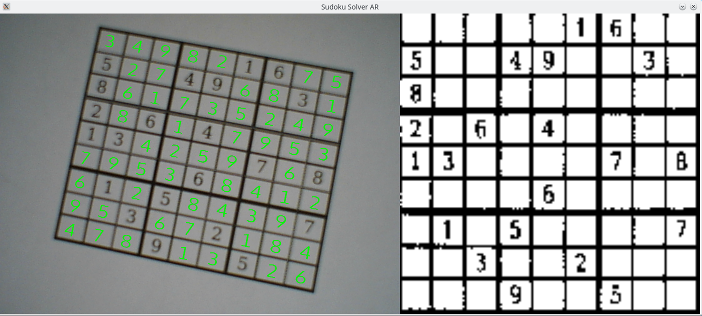
This is the start of a series of posts covering how to build an augmented reality Sudoku solver. The idea is to point a camera at a puzzle, have the computer find the puzzle, figure out which numbers are in which spots, solve the puzzle, and then display the answer over the original puzzle when displayed on a computer screen.
I’m going to be doing all of the processing from scratch. No computer vision libraries like OpenCV nor machine learning tools like TensorFlow will be used. This is an educational endeavor to cover how everything works. For serious projects, just use a battle tested library and save yourself the headaches.
Speaking of educational, there will be math. I plan to cover why things work and why sometimes they fall apart. You can scan past the parts you don’t understand but I’ll try to explain concepts or point you to places where you can develop a more detailed understanding.
All of the code is going to be in C++ and I’m going to assume basic knowledge of the STL. Using C++ means I can focus on writing clean code that’s also fast enough. Tuning for maximum performance is a lot of fun but it’s outside the scope of this project.
The source code for a complete working example can found on the Sudoku Solver AR GitHub page. The code is written for Linux and Windows but only the camera capture, window display, and some basic OpenGL parts are platform specific.
- About
- Sudoku
- A Crash Course in Image Processing
- Camera Capture (Linux)
- Camera Capture (Windows)
- Canny Part 1 (Gaussian Blur)
- Canny Part 2 (Sobel)
- Canny Part 3 (Non-Maximum Suppression)
- Canny Part 4 (Connectivity Analysis)
- Hough Transform
- Finding Lines
- Finding Puzzles
- Extracting the Puzzle
- Extracting the Digits
- Rendering Solutions
- Building Test Data
- OCR with Nueral Networks
- Compositing the Solution
subscribe via RSS